What can you do
after you have applied some basic energy saving techniques to
your house, such as CF lighting, reducing latent power,
insulation in the walls and roof, and switching to "Green
Power"? We asked ourselves this same question, and looked at our
electricity bill. It was obvious that heating was the dominant
factor in winter time. Could we heat our house better and
cheaper than our current oil heaters, or do something to
supplement them?
We did some
research and found that Solar Air Heaters looked quite
promising. The drawback was that prices for commercial units
were prohibitively expensive, approaching $3000. This seemed
excessive for what looked like a metal box with a couple of
fans, so we decided to research this field further and see if we
could design and build our own for significantly less. If
anything, it would be a load of fun and educational!
The result is the
Solar Sponge, an active Solar Air Heater which can be built for
under $500 installed with parts from the local hardware store.
As a bonus its performance equals or outperforms commercial
units of the same size!
How
It Works
Solar Air Heaters
come in two varieties, active and passive. The Active types use
fans to force the heat through the collector and ducting, while
passive types rely on thermal syphoning to circulate air through
the house. In both cases cooler air is extracted from either
outside or inside the house (at floor level), heated, and then
pumped back into the house. The passive type have very specific
requirements for mounting (usually outside a window to the
ground) so we opted for the more versatile active type which
could be mounted on the roof.
To start with you
need a collector, a box which collects the heat. The traditional
design for a solar collector comprises a black metal plate which
absorbs the solar radiation and converts it into heat, and a
sealed cavity on top to trap the heat within. This is
essentially how a “green house” works. The heat is extracted
from the back of the plate (via another sealed cavity) and
circulated by fans. This is often known as the “dead air space”
design.
That’s all there is
to it. Such designs have been around for many decades, and
commercial units are very popular in the US and Europe.
There are
variations on this basic design in which there is a single
enclosure of a metal box and a glass plate on top, and air is
pumped through this single sealed enclosure. However, this
design intrinsically has higher losses through the front plate,
which requires the use of expensive and fragile glass.
Pilkington SunPlus glass is designed for this purpose but is
very expensive, more expensive than our entire Solar Sponge
design and installation!
We opted for a
cheaper and simpler solution based on the traditional
dead-air-space design, but it was the choice our materials which
would prove to be the deciding factor in cost and ease of
construction.
Galvanised steel is
the traditional material used for such designs, but we opted for
Aluminium due to it having 4 times the thermal conductivity of
steel. In fact we built our entire collector box out of
aluminium, which made it easy to work with various pre-made
sheets and tubing sizes from the local hardware store.
Another key aspect
to the Solar sponge design is the use of very thin (<1mm)
polycarbonate sheeting for the front cover. This drastically
reduced our cost compared to glass or thicker 3mm polycarb
sheeting. Polycarbonate sheeting has similar transmissive
properties (around 90%) of the purpose designed low-iron SunPlus
glass, but at a fraction of the cost. It is also extremely tough
and can withstand hail. The thin material does however warp a
fair amount compared to thicker sheeting, but this had no
noticeable effect on the performance, and aesthetics weren’t
important to us.
The design of the
collector box was obviously crucial to the design. It needed to
be a certain minium size, and efficiently transfer the heat to
the air as it passes through. The design of any solar collector
will always be a rather delicate balance between air flow rate,
internal surface area, and losses to the outside world (back
through the polycarb cover plate and out the sides of the box).
Pump the air too fast through the collector and it won’t have
time to heat up, pump it too slow and it’ll get hot but the
volume won’t be there to heat your room, and heat losses will be
greater.
Somewhat contrary
to common sense, the hotter the collector plate the greater the
overall losses will be. So you want to actually minimise the
collector plate temperature by having sufficient air flow rate
and “heatsinking” within the design. The aluminium construction
of the solar sponge is fairly optimum at doing this. But you can
go overboard and have too much heat sink material, as being too
cool is bad too!
It was important to
have as long an air flow path as possible within the collector,
and also have the cold air being drawn in from the bottom of the
(angled) collector and coming out the top of the collector. Hot
air rises and we want to make use of that fact to improve our
efficiency. So the Solar Sponge was designed to be rectangular,
with the longer sides on the horizontal, the inlet port on the
bottom, and the outlet port on the top. Internal channels were
added to “snake” the air around the box, picking up heat as it
goes. With a 1.5m long box, this equates to a total air path of
4.5m, a length long enough to pick up sufficient heat. Holes
were also drilled on the bottom side on the internal square
channel walls to help break up the airflow.
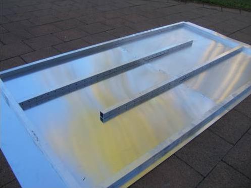

Back of the prototype with the ports in its wooden frame
We based our
prototype collector size on two 900x900mm pre-cut aluminium
sheets, giving us a total collector area of 1.6m2.
Although this is on the small side, it was suitable for a first
prototype.
 Fans
Fans
After initial
testing it
was obvious that fans are crucial to the design. They must be
the right capacity, use a minimum of
power, and
must be configured correctly based on the total ducting length.
Fans can be used in
parallel and in series. Fans in parallel will give an increase
in total airflow rate for low pressures (short ducts), but show
little gain at high pressures. Conversely, fans in series will
give a greater airflow rate at high pressures (long ducting),
but show little gain at low pressures. So there is no point in
having 4 fans in parallel on a long duct, as you won’t see much
improvement over 1 fan. The fan graphs shown illustrate this
concept. Fans are also rated into free air, so a 100CFM fan does
not produce 100CFM into a duct! In fact it will most likely be
1/10th
of that
value or less. This is important to know when it comes to energy
and efficiency calculations.
A typical solar
heater installation will have at least 5 meters of inlet and
outlet ducting, plus the collector itself (another 5m say). That
length of ducting is going to be “high resistance”, leading to
high pressure. So we need fans in series to increase our airflow
rate.
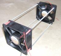
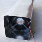 We
constructed two “fan boxes” wrapped in aluminium sheet each
using two 120mm x 38mm 12VDC 107CFM fans. There must be a
minimum distance between series fans to avoid any loss due to
air vortexes.
We
constructed two “fan boxes” wrapped in aluminium sheet each
using two 120mm x 38mm 12VDC 107CFM fans. There must be a
minimum distance between series fans to avoid any loss due to
air vortexes.
We used all the
fans on the outlet side ducting, but ideally they would be on
the inlet side to increase operational life (lower temperature).
Toxin Free
From the outset it
was important to us that the entire system be free of toxins.
After all, there was no point sitting in a warm house if you
were breathing in toxins!
This meant that the
entire air path (with the exception of the fans themselves) had
to be made of metal, including the collector box and the
ducting. Although we chose an all-aluminium construction of the
collector to improve thermal performance, this also happens to
be the perfect toxin free environment. Even the neutral cure
silicon used to seal the aluminium box is toxin free, and we
used Aluminium rivets to join it all together. The front of the
collect plate and the wooden frame are painted, but they are not
part of the air collection path.
Solar Power?
We (obviously)
thought about powering our fans from solar cells, but then
realised we already had “Green Power” so were already getting
solar and wind power. Not to mention that the cost of solar
cells (50W) would be prohibitive, with a payback period in the
order of 50 to 100 years.
What about Heat
Extraction?
Some designs allow
you to extract heat in summer as well. We looked at this but
decided that the extra complexity was not warranted considering
you can buy a simple exhaust fan for this purpose.
Construction
All of the parts to
build the Solar Sponge are available from your local hardware
store.
The
mechanical drawing and the photos
should have enough information to construct your own units.
Installation
The angle of the
collector to the sun is most important. However, as most
installations would be fixed, compromises have to be made. Some
designs have angled collector fins inside the box to supposedly
improve performance, but this is a false assumption. Angled fins
do not increase the total surface area relative to the sun.
Solar radiation will be absorbed the same from any angle.
We fixed the Solar
Sponge to the roof beams using 4 bendable metal mounting strips
that protrude from under the tiles. Although we found we needed
an extra wooden frame to extend the height of the collector.
Tile-tites were used to replace the roof tiles and allow the
ducting to penetrate the roof.

During testing we
found that having our inlet on the ceiling along with the outlet
(even with them in different rooms) we got a laminar flow across
the ceiling which was very inefficient. Ideally you want the
inlet on the floor level, but our house design did not allow
this.
So in the end we
simply disconnected the inlet duct and drew air in from the
outside. As a bonus we now have shorter ducting, fresh air
circulation, and no laminar flow problems.
This however may
not work in all climates.
Conclusion
Based on initial
result graph I don’t think we have yet reached the maximum air
flow rate for our particular collector size, some more research
will have to done in this area.
The design at
present does not have a controller for automatic operation. But
we plan to add a simple temperature sensor to the collector
plate to automatically switch on the fan when the sun hits the
collector.
Unfortunately we
just finished the Solar Sponge at the end of winter, and the
warmest winter on record to boot! So we didn’t have much time to
put it to real use. However, the results we got were quite
encouraging for such a small collector. Whilst the prototype
Solar Sponge worked fairly well, we feel that it was a little on
the small side (1.6m2) for our large living area.
Typical
heat output was in the order of 500W on an average day.
Not bad for a mere 25W of fan power!
This Graph shows a 3°C increase in our main living room
temperate which is quite impressive for such a small collector.
The prototype has
shown us that Solar Air Heaters are a viable technology and can
be made cheaply. It sure is nice sitting under a vent pumping
out 40°C air. We can’t wait for next winter!
Return to the
Main Page